The Roof-Form Extraction process is run in the first step of the Publish Schematic Buildings task. It uses lidar derived surface model rasters and vector building footprints to find both flat and sloped planar areas within a roof area of a building. The tool then estimates a standard architectural form for the roof based on the attributes collected from these planar surfaces. These attributes are then used to inform a procedural rule that generates these features in 3D.
The process accomplishes the following:
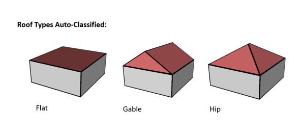
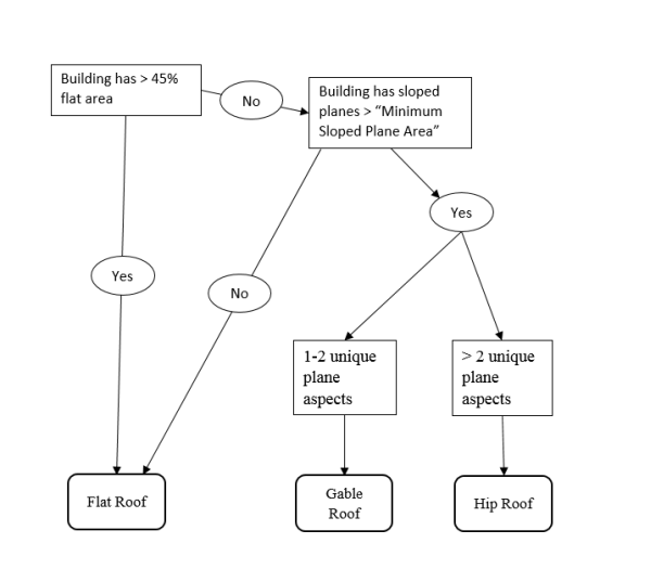
- Populates the ROOFFORM field of the building footprints with a basic architectural type (see above for supported roof types) based on the decision tree in the figure below.
- For sloped roof types (all except Flat), the EAVEHEIGHT field is calculated to be the lowest elevation found in the DSM of the largest sloped roof plane detected.
- For Shed and Gable roof types, the ROOFDIR field is populated giving the compass direction that the shed roof slope faces, and the direction that a gable roof ridge faces.
The output of this tool is a building footprint feature class with the above fields populated, and an initial output of 3D buildings constructed using these attributes.
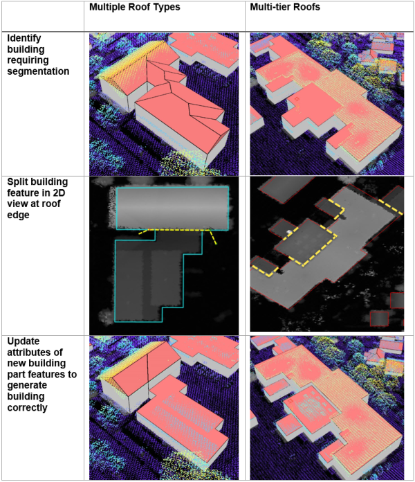
Roof Segmentation
Some building footprints may contain several different roof types and roof parts. To accurately represent these buildings, you need to split the footprints into separate features before you extract roof forms. Use the tools in the Preprocess Buildings task to optionally split the building footprints before roof form creation.
Split Buildings using Features allows you to split building footprints using other features. Use this tool if the split features delineate differences in height and/or roof types, for example, parcel boundaries in dense urban areas.
Segment Roofs allows you to automatically split building footprints using differences in the underlying elevation. This step uses image classification techniques to identify unique segments within the DSM, and geometry regularization methods to enforce right angles and diagonals in the output polygons generated from these segments. The height of the output segments are then derived from their average height within the DSM. The Spectral Detail, Spatial Detail, and Minimum Segment Size parameters control how fine or coarse this segmentation occurs, and the defaults are derived from the extent of the input building footprints, and the cell size of the input DSM. These parameters may be updated to achieve a desired level of detail.
Quality control
Run the Review Building Roof Forms step in the Publish LOD2 Buildings task to perform a visual inspection on your data. Use the results from the Confidence Measurement tool to guide your review of the Roof-Form Extraction process results. The Confidence Measurement tool reports the following measurement (attribute added to the building footprints):
- RMSE: This field shows the root-mean-square-error of the generated building multipatch to the underlying surface model. The higher this number, the more likely that the roof-form extraction process encountered an error in classification. In general, a value of 1 meter (3.3ft) or less is desirable, though this depends on the required application of the output features, and the resolution of the input data.
Refine building roof form
The building roof form is driven by the attributes that are generated by the Roof-Form Extraction process and by the underlying the building footprint. To refine the building roof form, modify the attributes and/or the building footprint.
Modify roof form attributes
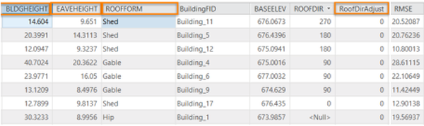
The attributes that control the roof form are building height, eave height, roof direction, and the type of roof (BLDGHEIGHT,EAVEHEIGHT, ROOFFORM, RoofDirAdjust). By editing these attributes, you can adjust your building models to better match the lidar data.
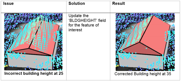
Building Height (BLDGHEIGHT)
- If the ridge of the building is not at the correct height, identify the elevation of a LAS point on the true ridge by clicking on the LAS point while having the Explore tool active.
- Subtract the BASEELEV value from the LAS elevation to get the correct BLDGHEIGHT value.
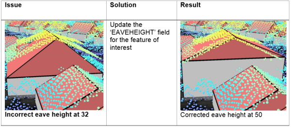
Eave Height (EAVEHEIGHT)
- Similar to building height, reference the lidar to obtain the correct eave height.
- Subtract the BASEELEV from the lidar elevation to get the correct the EAVEHEIGHT value.
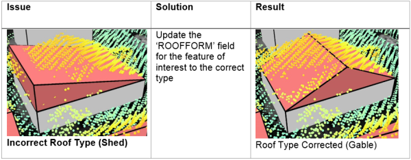
Roof Form (ROOFFORM)
- If your roof type does not match the lidar data, change the roof type by choosing the correct roof form from the drop-down menu.
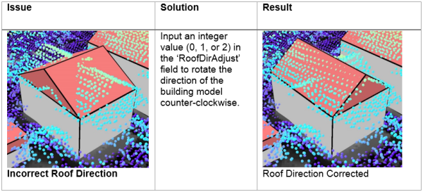
Roof Direction (RoofDirAdjust)
- Adjust the direction of the roof by modifying the RoofDirAdjust field. The default value is 0. A value of 1 will rotate the roof counter-clockwise 90 degrees or 2 will rotate it 180 degrees.
Manual roof segmentation
Some building footprints may contain several different roof types and roof parts. To accurately represent these buildings, you can split the footprints into separate features manually and update the attributes for each feature accordingly.
To edit the building footprints, complete the following steps:
- Select the feature you wish to segment.
- Use the Split tool in the Roof Segmentation task, or on the Modify Features pane to segment the selected feature.
- Edit the attributes as needed with the new sections of the building footprint.
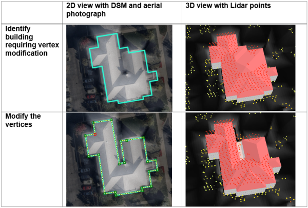
Modify building footprint vertices
Sometimes building footprints may have been created incorrectly and do not represent the building adequately, resulting in lower quality roof forms.
To edit the building footprints, complete the following steps:
- Select the feature you wish to modify.
- Use the Vertices tool in the Modify Building Vertices task, or on the Edit tab to modify the selected feature.
- Edit the attributes as needed with the modified building footprint.
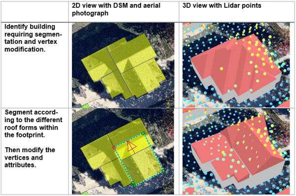
You can also use vertex editing to make cross gable roof forms, by completing the following steps:
- Select the feature you wish to modify.
- Use the Split tool in the Roof Segmentation task, or on the Edit tab to segment the building footprint according to the roof forms present within the footprint.
- Use the Vertices tool in the Modify Building Vertices task, or on the Modify Features pane to extend one gable roof into the other one.
- Edit the attributes as needed with the modified building footprint.
Fuse roof form segments
If you have segmented some building footprints into separate features, you can use the Fuse Roof Form Segments task to fuse the building features that represent building parts, back together in the resulting 3D building features.