The Point of Origin Detection template includes sample data so you can easily try out the tool.
- The template opens in Layout View showing you an example of a finished Point of Origin Map with an inset map. Before you begin using the template you will want to switch to Map_Results tab.
- Explore the sample Point of Origin Results in the Table of Contents:
- The Sample Point of Origin Results Group layer will contain the following
- Point of Origin Results\Impact Points represents the known impact points and are used as inputs to the Point of origin Site Detection tool.
- M120121_120mm_American_Mortar Group Layer
- The M120121_120mm_American_Mortar Point Of Origin represents the Point of Origin areas where indirect fires could have originated
- The M120121_120mm_American_Mortar by Impact OID layers show the minimum and maximum range rings of the suspected weapon system related to each Point of Impact. Each is named with prefix and the ID number of impact point (OID)
- Now that you are familiar with the analysis results that the Point of Origin tool creates you can turn off these sample results in the Table of Contents and use your own Impact Points feature class.
- Open the Point of Origin Site Detection Task
- Review the 3 Steps in the Task list.
- 1. Overview - Provides information about the inputs for the Point of Origin Detection Tool
- Click Next Step
- 2. Point of Origin Detection Tool - when this step is run, the Tool will be launched in separate undocked form. The input parameters are explained in Step 1 of the ArcGIS Pro Task.
- Click Run
- When Geoprocessing is finished - Click Next Step
- 3. User examines symbology for Point of Origin Results - User can use ArcGIS Pro Appearance tab group to adjust symbology and transparency of layers.
- Click Finish
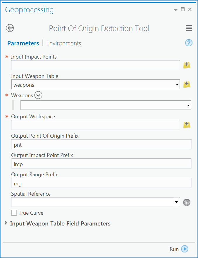
- While running the Geoprocessing Tool there are a few required input parameters (red asterisk) and optional settings to you can use.
- You will need to specify a point feature class for the "Input Impact Points".
- Select the "Input Weapon Table" - default is the sample "Weapons" table in the Point of Origin geodatabase. Modify this table or create one of your own
- Under "Weapons", a drop down menu is available to select weapon type for the analysis.
- For "Output Workspace" you need to specify the file GDB to store the results.
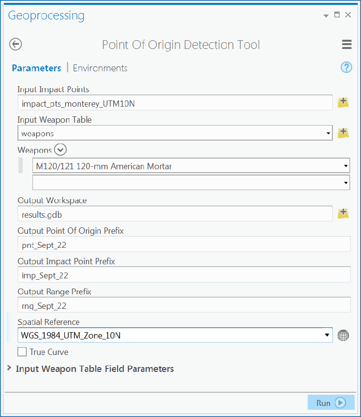
- You can use default or set a string to use as a prefix for the three result outputs - the "Output Point of Origin", default is "pnt", "Output Impact Point Prefix" default is "imp", and "Output Range Prefix" default is "rng". See example form below.
- You must also specify an Coordinate System for the results, you cannot use Geographic for the analysis
- You can check the box for "Use True Curves" or leave it unchecked which will result in polygons. Polygons are desirable if you plan to project you Map on the fly to other Projected Coordinate Systems"
- Optionally, add additional information – such as historical Point of Origin sites, built up areas, elevation constraints, etc – with the results from the tool to determine most likely areas of origin. Use the inset map to highlight these areas.
- Optionally, add your own artillery information to the "Weapons" table, or specify your own table. If using a different table the Point of Origin Detection Tool allows for specifying "Model", "Minimum_Range", and "Maximum_Range"
Examples of Point of Origin Tool as first opened showing required input (red asterisk), and example filled in and ready to run with modified optional settings.