Once you've created a geometric network, cleaned up any flagged errors, and generated the isolation trace toolbox, there are a few more steps to complete before you can use the Utility Isolation Trace app.
Configure the Utility Isolation Trace app
- In ArcGIS Online, browse to the Utility Isolation Trace app item details page.
- From the Overview tab on the Utility Isolation Trace app, click Edit Application.
- Click the Widget tab to review the widget settings.
- Click the controller to open the page for in-panel widgets. Click the add button to open the widget collection, where you can select and add widgets to the application.
- In the Choose Widget window, search for the Network Trace widget and click OK.
- Set the Task URL option to your geoprocessing service, and update the remaining project settings as shown in the following table:
Parameter name Setting Project polygon layer
Outage Area
Output parameter name
Result Area
Project point layer
Project Inputs
- Click the Input/Output tab.
- In the Input Settings section, update the ToolTips and symbols for Flags, Barriers, and Skip Locations.
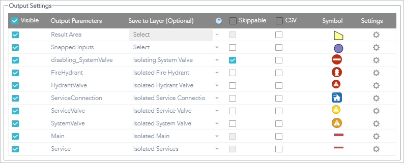
- In the Output Settings section, use the following image as a guide for the recommended settings and optional symbology:

- Each of the layers has additional settings to control the Label and Display text for the trace results. The following table below shows the recommended settings for each of the Output Parameters:
Output parameters Label Display text Result Area
Result Area
Result Area
Snapped Inputs
Snapped Inputs
{INPUTTYPE}
disabling_SystemValve
Isolating System Valve
{assetid}
FireHydrant
Isolating Hydrant
{assetid}
HydrantValve
Isolated Hydrant Valve
{assetid}
ServiceConnection
Isolated Connection
{assetid}
ServiceValve
Isolated Service Valve
{assetid}
SystemValve
Isolated System Valve
{assetid}
Main
Isolated Main
{diameter}
Service
Isolated Service Lateral
{diameter}
- Click the General Settings tab, then update the Summary text section with the following text:
- {disabling_SystemValve:Count} Valve(s) to close
- {FireHydrant:Count} Hydrant(s) without service
- {ServiceConnection:Count} Connection(s) without service
- {skip_locations:Count} Valve(s) skipped
- In the Additional Options section, select the Auto zoom after trace option and click OK.
- Click the Open this widget automatically when the app starts button
 on the widget.
 The button turns dark green.
- Click Save.
Set the custom trace URL in the Leak Investigator map
Setting a custom trace URL in the Leak Investigator map allows field workers investigating leaks to open the Utility Isolation Trace app and run the trace from the location of a validated leak.
- In ArcGIS Online, browse to the Leak Investigator map item details page.
- From the Overview tab on the Leak Investigator map, click Open in Map Viewer.
- Click Details, and click Contents.
- Browse to the Leak Issues layer, click More Options
 , and click Configure Pop-up.
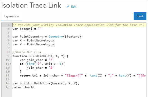
 - Under Attribute Expressions, select Isolation Trace Link, and click Configure expression
 to open the editor.
 - In the editor, copy the Utility Isolation Trace app link between the double quotation for baseurl variable.

- Click OK when you're finished.
- In the Configure Pop-up pane, click OK.
- Click Save at the top of Map Viewer Classic to save the pop-up changes to the map.